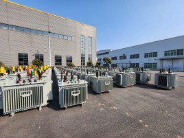
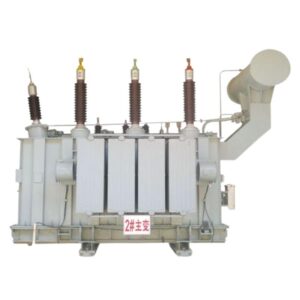
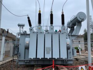
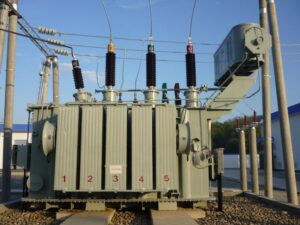
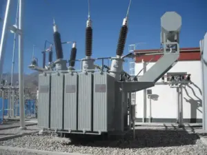
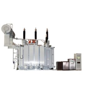
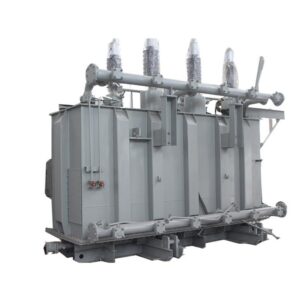
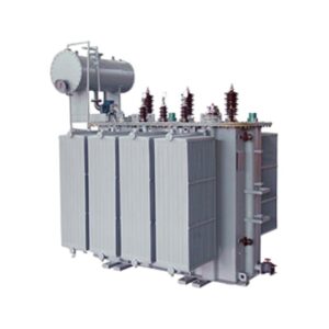
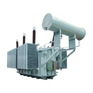
110KV class three phase oil immersed power transformer
Primary Voltage Ratings:110KV,115KV,121KV or others
Second Voltage Ratings:0.4KV or others
Rated power: 6300kva to 63mva
Winding connection: Ynd11/YNyn0
H.V. TAP RANGE: ±2×2.5% /±8×1.25% or others
Tapping Method: OLTC/NLTC All available
Standards: IEC60076, GB/T 6451, ANSI, IEEE
Min. order quantity: ≧ 1 set
Packaging Details: International wooden cases or according to the actual transport needs
delivery time: Generally it is 20 days if the goods are in stock, or 30 days if the goods are not. It is according to the quantity.
Payment Method: TT, Western Union, L/C
The 110kV power transformer developed and produced by GE Transformer draws on advanced technology at home and abroad. Its reliability and performance have reached the international advanced level. It has the characteristics of environmental protection, economy, and strong stability. It is suitable for substations, power plants, large industrial and mining enterprises, etc. GE Transformer has the development and production capacity of 110kV power transformers, traction transformers, split transformers, and other standard and non-standard products. These excellent products have reached the international advanced level and have been widely used in the State Grid, China Southern Power Grid, and overseas power systems. We have won high recognition from market users and industry experts. With years of rich manufacturing and operation experience, we are committed to providing high-quality products and services for power systems.
110KV oil immersed transformer performance features
- Low loss
The no-load loss is 15%-20% lower than the national standard GB64511, and the load loss is 5% lower than the national standard GB6451-2008.
2. Low noise
The self-cooling noise level will reach below 60dB, which is nearly 20dB lower than the national standard and can be specially designed and manufactured with lower noise levels if users have special requirements. - Low local discharge
The whole process of 110kV products will be dust-free, and all metal and insulating parts inside the body will be rounded so that the amount of local discharge will be controlled below 100pc. - High short-circuit resistance
110kV transformers are certified to have strong short-circuit resistance and reliability. - Beautiful appearance
Full polishing and grinding to remove rust, powder electric spray paint can reach the effect of appliance spray paint, wide piece radiator. - No leakage
All seals are made of acrylate material and adopt one-time molding technology, with no interface.
110KV power transformer process characteristics
- Insulation
High-temperature resistant hybrid insulation system winding. - Coils
High-voltage coils of small and medium capacity are tangled one by one continuous type, and large easy for the inner screen one by one continuous type, in order to improve the longitudinal capacitance distribution of the coil under the shock voltage; coils are guided oil circulation structure, reduce the temperature rise of the winding, product design life of 30 years. - Iron core
High permeability voltage-oriented cold-rolled silicon steel sheet will be used, non-porous tying, frame structure, D-shaped iron yoke structure for the coil to provide a large area platform, step-level seam. Swiss imported automatic shearing and stacking robots ensure that the burr of the core is less than 20µm, and the multi-stage seam of the core reduces the no-load loss and lowers the no-load current and noise level. - Oil tank
Minute cover type and barrel type structure. All seals are stop-hole limit seals; all metal parts inside and outside the tank are rounded and deburred, welds and seals are leak tested three times (fluorescent, positive pressure, and negative pressure leak tests); paint is made according to the rust-proof requirements of home appliances.
| 6300kVA~180000KVA 3-PHASE DUPLEX WINDING NLTC POWER TRANSFORMER | |||||||
| Rated power (kVA) | Voltage Combination and Tap range | Connection Symbol | S11 Loss(kW) | No-load current (%) | short-citcuit Impedance (%) | ||
| HV (kV) | LV (kV) | No-load | Load | ||||
| 6300 | 110±2×2.5% 115±2×2.5% 121±2×2.5% | 6.3 6.6 10.5 | YNd11 | 5.9 | 33 | 0.62 | 10.5 |
| 8000 | 7.1 | 40 | 0.62 | ||||
| 10000 | 8.4 | 48 | 0.58 | ||||
| 12500 | 9.9 | 56 | 0.58 | ||||
| 16000 | 12.0 | 69 | 0.54 | ||||
| 20000 | 14.1 | 84 | 0.54 | ||||
| 25000 | 16.6 | 99 | 0.50 | ||||
| 31500 | 19.7 | 117 | 0.48 | ||||
| 40000 | 23.5 | 141 | 0.45 | ||||
| 50000 | 13.8 15.75 18 21 | 28.2 | 166 | 0.42 | |||
| 63000 | 33.3 | 198 | 0.38 | ||||
| 75000 | 37.8 | 224 | 0.33 | 12~14 | |||
| 90000 | 43.5 | 258 | 0.30 | ||||
| 120000 | 54.2 | 320 | 0.27 | ||||
| 150000 | 64.1 | 379 | 0.24 | ||||
| 180000 | 72.0 | 434 | 0.20 | ||||
| Note 1:-5 tap position is the maximum current tap Note 2: For step-up transformers, Non-tap structure is suitable According to requirements, taps can be set. | |||||||
| 6300kVA~63000kVA 3-PHASE 3-WINDING NLTC POWER TRANSFORMER | |||||||||
| Rated power (kVA) | Voltage Combination and Tap range | connection Symbol | S11 Loss(kW) | No-load current (%) | short-citcuit Impedance(%) | ||||
| HV (kV) | MV (kV) | LV (kV) | No-load | Load | Step wp | Step down | |||
| 6300 | 110±2×2.5% 115±2×2.5% 121±2×2.5% | 36 37 38.5 | 6.3 6.6 10.5 21 | YNyn0d11 | 7.1 | 42 | 0.66 | HV-MV 17.5~18.5 HV-LV 10.5 MV – LV 6.5 | HV-MV 10.5 HV-LV 18~19 MV-LV 6.5 |
| 8000 | 8.5 | 50 | 0.62 | ||||||
| 10000 | 10.1 | 59 | 0.59 | ||||||
| 12500 | 11.8 | 70 | 0.56 | ||||||
| 16000 | 14.3 | 86 | 0.53 | ||||||
| 20000 | 16.9 | 101 | 0.52 | ||||||
| 25000 | 19.7 | 120 | 0.48 | ||||||
| 31500 | 23.5 | 142 | 0.48 | ||||||
| 40000 | 27.8 | 170 | 0.44 | ||||||
| 50000 | 33.3 | 202 | 0.44 | ||||||
| 63000 | 39.4 | 243 | 0.40 | ||||||
| Note 1: High, medium, and low voltage winding capacity distribution(100/100/100)%; Note 2: According to requirements, the vector group can be Ynd11y10 Note 3: According to requirements, the medium voltage can choose different voltage from the value listed in the table or set taps. Note 4: 5% tap position is the maximum current tap; Note 5: for step-up transformers. Non-tap structure is suitable, According to requirements, the tape can be set. | |||||||||
| 6300kVA~63000kVA 3-PHASE DUPLEX WINDING LV 35kV NLTC POWER TRANSFORMER | |||||||
| Rated POWER (kVA) | Voltage Combination and Tap range | Connection Symbol | S11 Loss(kW) | No-load current (%) | Impedance Voitage (%) | ||
| HV (kV) | LV (kV) | No-load | Load | ||||
| 6300 | 110±2×2.5% 115±2×2.5% 121±2×2.5% | 36 37 38.5 | YNd11 | 8.00 | 37 | 0.67 | 10.5 |
| 8000 | 9.60 | 44 | 0.67 | ||||
| 10000 | 11.20 | 52 | 0.62 | ||||
| 12500 | 13.10 | 62 | 0.62 | ||||
| 16000 | 15.60 | 76 | 0.57 | ||||
| 20000 | 18.50 | 94 | 0.57 | ||||
| 25000 | 21.90 | 110 | 0.53 | ||||
| 31500 | 25.90 | 133 | 0.53 | ||||
| 40000 | 30.80 | 155 | 0.49 | ||||
| 50000 | 36.90 | 193 | 0.49 | ||||
| 63000 | 43.60 | 232 | 0.45 | ||||
Note: 1 Products with capacity not included in this form will be also available based on the requirement of the user, and their performance data will rely on specific requirement 2 We can provide products with a special design according to different operation environments. 3 Customers can suggest their requirement of MV and tap range besides the form and the asymmetry tap range are available for HV tap regulation choice 4 Different impedance Voltage Values are available for the customer’s choice besides the value in the form. 5 The final dimension will be subject to the drawing which designed after the contract signs | |||||||
| 6300kVA~63000kVA 3-PHASE DUPLEX WINDING OLTC POWER TRANSFORMER | |||||||
| Rated Power (kVA) | Voltage Combination and Tap range | Connection Symbol | S11 Loss(kW) | No-load current (%) | Short circuit Impedance (%) | ||
| HV (kV) | LV (kV) | No-load | Load | ||||
| 6300 | 110±8×1.25% | 6.3 6.6 10.5 21 | YNd11 | 6.4 | 33 | 0.64 | 10.5 |
| 8000 | 7.7 | 40 | 0.64 | ||||
| 10000 | 9.0 | 48 | 0.59 | ||||
| 12500 | 10.7 | 56 | 0.59 | ||||
| 16000 | 12.9 | 69 | 0.55 | ||||
| 20000 | 15.4 | 84 | 0.55 | ||||
| 25000 | 18.2 | 99 | 0.51 | ||||
| 31500 | 21.6 | 117 | 0.51 | ||||
| 40000 | 25.8 | 148 | 0.46 | 12~18 | |||
| 50000 | 30.6 | 184 | 0.46 | ||||
| 63000 | 36.3 | 220 | 0.42 | ||||
| Note 1: For on-load tap-changing transformers, now only step-down structure products are provided; Note 2: According to requirements, other voltage combinations can be provided. Note 3:-10%tap position is the maximum current tap. | |||||||
| 6300kVA~63000KVA3-PHASE 3-WINDING OLTC POWER TRANSFORMER | ||||||||
| Rated power (kVA) | Voltage Combination and Tap range | Connection Symbol | S11 Loss(kW) | No-load current (%) | Short-circuit Impedance (%) | |||
| HV (kV) | MV (kV) | LV (kV) | No-load | Load | ||||
| 6300 | 110±8×1.25% | 36 37 38.5 | 6.3 6.6 10.5 21 | YNyn0d11 | 7.7 | 42 | 0.76 | HV-MV 10.5 HV – LV 18~19 MV – LV 6.5 |
| 8000 | 9.2 | 50 | 0.76 | |||||
| 10000 | 10.9 | 59 | 0.71 | |||||
| 12500 | 12.9 | 70 | 0.71 | |||||
| 16000 | 15.4 | 86 | 0.67 | |||||
| 20000 | 18.2 | 101 | 0.67 | |||||
| 25000 | 21.6 | 120 | 0.62 | |||||
| 31500 | 25.7 | 142 | 0.62 | |||||
| 40000 | 30.8 | 170 | 0.58 | |||||
| 50000 | 36.4 | 202 | 0.58 | |||||
| 63000 | 43.3 | 243 | 0.53 | |||||
| Note 1: For on-load tap-changing transformers, now only step-down structure products are provided; Note 2: High, Medium, and low voltage winding capacity distribution(100/100/100)%; Note 3: According to requirements, the vector group can be YNd11y10; Note 4: 10%tap position is the maximum current tap; Note 5: According to requirements, medium voltage can choose different voltage from the value listed in the table or set taps. | ||||||||
Related Products


Related Article
Top 10 Power Transformer Manufacturers in the World: Global Leaders & Trends
The Ultimate Guide to Three-Phase Transformer: Design, Connections, and Efficiency
The Differences Between Power Transformers and Distribution Transformers: Essential Comparisons & Key Details