Three-phase transformers keep the electrical grid humming. They power factories, office buildings, and, honestly, whole cities.
These devices step voltage up or down across three-phase systems. That makes it possible for power plants to generate electricity and deliver it safely to your facility.
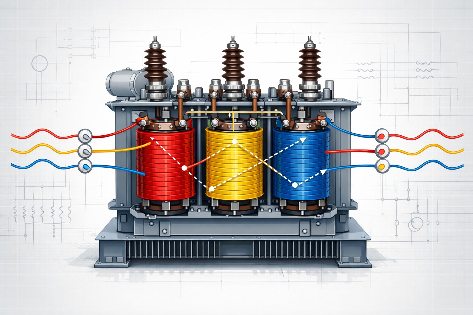
A three-phase transformer uses three sets of windings to efficiently convert high voltage electricity for transmission over long distances. Then, it brings it down to usable levels for your equipment and operations.
If you understand how three-phase transformers work, you can pick the right equipment for your needs. Maybe you’re eyeing a pad-mounted transformer for a busy commercial site. Or you need a pole-mounted unit for rural distribution.
Knowing the differences between delta and wye connections really matters. The setup you pick affects voltage output, load balancing, and even the reliability of your whole system.
This guide dives into everything from basic construction to some pretty advanced winding configurations. You’ll see info on transformer types, connection methods, performance details, and practical applications.
Key Takeaways
- Three-phase transformers efficiently convert voltage levels in electrical power systems through three sets of primary and secondary windings.
- Different connection types like delta-delta, delta-wye, wye-delta, and wye-wye serve specific applications based on voltage requirements and load conditions.
- These transformers offer advantages including balanced loading, improved reliability, and reduced material costs compared to single-phase alternatives.
Fundamentals of Three-Phase Transformers
Three-phase transformers run on electromagnetic induction between primary and secondary windings. Magnetic flux links the coils and moves energy from one side to the other.
The turns ratio sets the voltage ratio between phases. Phase displacement and phase sequence decide how the three-phase power gets delivered to your load.
Working Principle and Magnetic Flux
The three-phase transformer working principle is all about electromagnetic induction. When you apply alternating voltage to the primary winding, it creates a magnetic flux in the transformer core.
This magnetic flux alternates at the same frequency as your input voltage. It flows through the iron core and links both the primary and secondary windings.
As the flux cuts through the secondary winding, it induces a voltage—thanks, Faraday’s law. The number of turns in each winding decides the voltage you get out.
In a three-phase transformer, you’ve got three separate magnetic flux paths—one for each phase. These paths are 120 degrees apart in time.
This setup lets you transform three-phase power efficiently, either in a single unit or using three single-phase transformers wired together.
Primary and Secondary Windings
Your three-phase transformer contains three primary and three secondary windings for each phase. Each primary winding connects to one phase of your incoming circuit.
Each secondary winding gives you one phase of the outgoing power. The turns ratio between primary and secondary windings sets your voltage transformation.
Say your primary winding has 1,000 turns and your secondary has 500. That’s a 2:1 ratio, so your output phase voltage is half the input.
Your phase voltage and line voltage aren’t always the same. In a delta connection, they match. In a wye connection, line-to-line voltage is 1.73 times higher than phase-to-neutral voltage.
Phase current and line current also change depending on the connection type.
Phase Displacement and Phase Sequence
Phase displacement is just the angular difference between primary and secondary voltage phasors. Different winding connections create different phase shifts.
A delta-wye connection usually gives a 30-degree phase shift. Phase sequence tells you the order in which the three phases reach their peaks—ABC (positive) or CBA (negative).
Get the sequence wrong and motors might run backward or relays could trip. You can check phase sequence with a phase rotation meter before you flip the switch.
When you parallel transformers, match both phase displacement and sequence. That way, the load shares properly and you avoid circulating currents.
Transformer Construction, Types, and Core Structures
Three-phase transformer construction comes down to core design, winding arrangement, and materials. The core structure shapes how magnetic flux flows, and the construction type impacts size and kva ratings.
Core Type and Shell Type Designs
The two main transformer construction designs are core type and shell type. In core type, windings wrap around the core legs. The core guides the magnetic flux, while the coils surround it.
Shell type transformers flip that. The core surrounds the windings, which sit on the center leg. The magnetic circuit wraps around them, protecting the windings.
Core Type Features:
- Windings on each leg of the core
- Easy to maintain and repair
- Better cooling for windings
- Common for high-voltage jobs
Shell Type Features:
- Windings stacked on center leg
- More mechanical protection
- Lower leakage flux
- Compact design
You’ll notice core type designs use barrel windings, while shell type usually uses pancake windings. Which you pick depends on voltage, power, and space.
Windings and Core Materials
The core uses laminated silicon steel sheets to keep eddy current losses down. These thin layers get stacked with insulation between each sheet.
The laminated core design helps keep core loss low. Winding materials are either copper or aluminum.
Copper carries current better but costs more. Aluminum is lighter and cheaper, but you need a thicker wire for the same current.
Windings must handle the voltage and current without overheating. Primary and secondary windings get placed to maximize magnetic coupling.
In barrel-type construction, the high-voltage coil sits outside the low-voltage coil.
Types of Three-Phase Transformers
You can build three-phase systems using a bank of three single-phase transformers or a single integrated three-phase unit. A transformer bank gives you flexibility—if one fails, just swap it out.
Single three-phase transformers combine all three phases into one magnetic circuit. That saves space and material, and it usually costs less to install.
Both step-up and step-down configurations work with either style. Step-up boosts voltage for long-distance transmission, while step-down brings it down for distribution.
Your choice depends on whether you value redundancy or space efficiency more.
Winding Connections and Configurations
Three-phase transformers use specific winding arrangements that set voltage ratios, phase relationships, and grounding options. The windings can connect in delta or wye patterns, and the setup changes neutral point availability and system performance.
Delta and Wye (Star) Connections
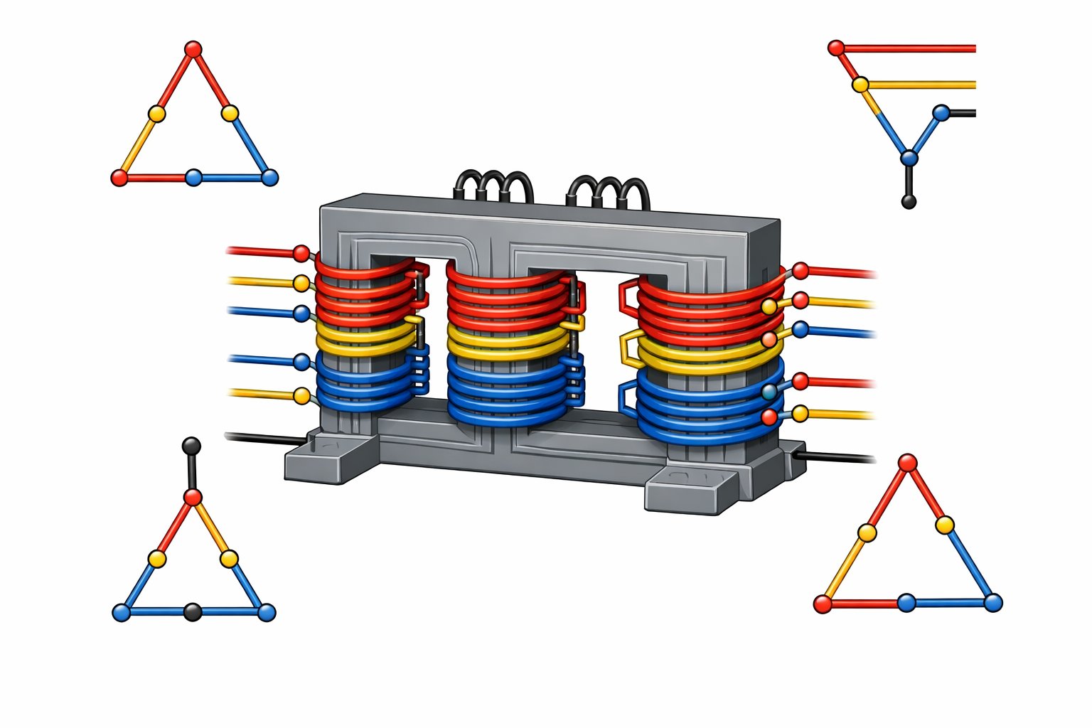
The two main three-phase transformer connections are delta and wye. In a delta connection, you wire three windings in a closed triangle.
This delta setup means line and phase voltages are equal, but line current is √3 times the phase current. In a wye configuration (or star/Y connection), you join one end of each winding at a common neutral point. The other ends get the three-phase supply.
This gives you a neutral for grounding. Line voltages end up √3 times higher than phase voltages.
Key differences between connections:
| Feature | Delta | Wye (Star) |
|---|---|---|
| Neutral point | Not available | Available |
| Line voltage | Equals phase voltage | √3 × phase voltage |
| Line current | √3 × phase current | Equals phase current |
| Grounding | Cannot ground | Supports neutral grounding |
Delta-Wye and Wye-Delta Variants
Combine different winding connections on primary and secondary sides, and you get hybrid setups. A delta-wye connection uses delta on the primary and wye on the secondary. That gives you a 30-degree phase shift, plus neutral grounding on the secondary.
The wye-delta variant flips it—wye on the primary, delta on the secondary. Both handle unbalanced loads better than wye-wye connections.
The delta winding lets third harmonic currents circulate without showing up in the output voltage. The phase sequence shifts by 30 degrees in these setups. You can wire them for a +30-degree or -30-degree shift, depending on your needs.
This phase relationship matters when you parallel transformers or hook into existing systems.
Open-Delta (V-V), Zig-Zag, and Scott-T Connections
The V-V connection (open-delta) lets you use just two transformers to keep three-phase power running if one transformer fails in a delta-delta system.
With this setup, you can deliver about 57.7% of the original three-phase capacity. Each remaining transformer runs at 173.2% of its usual rating when you put the full V-V load on it.
A zig-zag connection ties together windings from different phases to make a neutral point with stronger grounding.
This setup helps cut down voltage imbalances and gives you better zero-sequence impedance than a standard wye connection.
The Scott-T connection changes three-phase power into two-phase power using two specially arranged transformers.
One’s the main transformer, and the other—called the teaser—is rated at 86.6% of the main unit. You’ll see this oddball connection show up for legacy two-phase gear or in a few niche industrial processes.
Performance, Parallel Operation, and Applications
Three-phase transformers usually hit efficiency levels above 95% because they keep losses low. Parallel operation makes it easier to share loads and boosts system reliability.
That’s why you see them everywhere in power transmission, distribution, and even for tying in renewables.
Transformer Efficiency and Power Losses
Your transformer’s efficiency really depends on how well it cuts down on energy losses.
Copper loss happens in the windings whenever current flows, thanks to resistance. These I²R losses jump up fast as current increases.
Hysteresis loss shows up in the core as the magnetic domains flip back and forth with each AC cycle.
Eddy current losses also pop up in the core when little circulating currents form in the laminated steel.
You can figure out transformer efficiency with this formula:
Efficiency = (Output Power / Input Power) × 100%
Most power transformers run at 96-99% efficiency when fully loaded. Distribution transformers usually land between 95-98%.
Core losses stay about the same even when unloaded, but copper losses climb as you add load.
The magnetizing current only pulls about 2-5% of rated current and adds to core losses.
It’s worth keeping an eye on these losses—they create heat and can drag down system performance.
Voltage Regulation and Tap Changers
Voltage regulation tells you how much the secondary voltage drops from no-load to full-load.
Here’s the formula:
Voltage Regulation = [(No-Load Voltage – Full-Load Voltage) / Full-Load Voltage] × 100%
Lower voltage regulation is better—under 5% is good for most uses.
A tap changer tweaks the turns ratio to help keep voltage steady.
There are two main types:
- Off-load tap changers—you have to shut down the transformer first
- On-load tap changers—you can adjust these while the transformer is running
On-load tap changers usually give you ±10% voltage adjustment in 1.25% or 2.5% steps.
You’ll see them in transmission systems where you need constant voltage control. Buchholz relays keep an eye on the tap changer compartment, watching for gas or oil movement that could mean trouble inside.
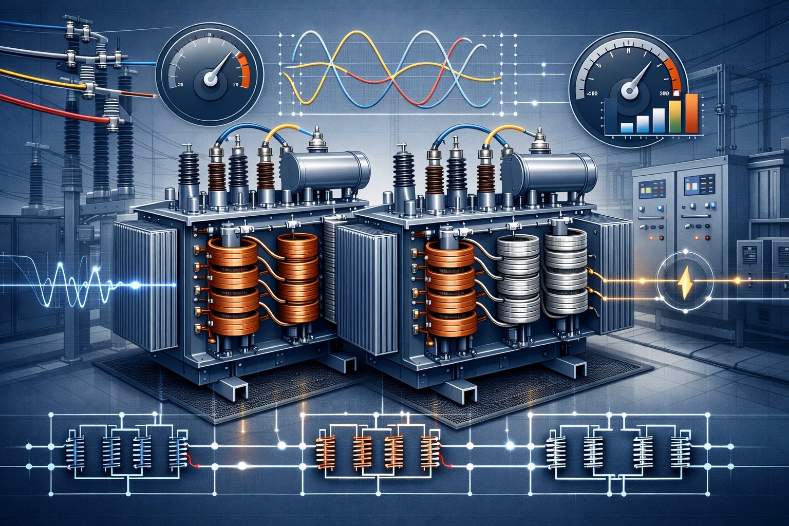
Parallel Operation and Load Sharing
Running transformers in parallel means hooking up two or more to share the total load.
But you need to meet a few conditions to make it work right.
Transformers should have the same voltage ratio and turns ratio. If not, circulating current can flow between them, even with no load, which just creates heat and wastes energy.
Matching percentage impedance is key for proper load sharing. Each transformer will carry current inversely proportional to its impedance.
You get balanced loading when transformers have:
- Matching voltage ratios
- Same percentage impedance
- Equal X/R ratios
- Identical phase sequence
- Matching polarity
Connect transformers with equal impedances and ratings, and they’ll split the load evenly. If their ratings differ, their impedances should be inversely proportional to their kVA ratings for fair load sharing.
Why run them in parallel? Here’s why:
- You get more reliability because of redundancy
- Maintenance is easier—no need to shut down everything
- Spare units cost less
- You can add capacity bit by bit as demand grows
Applications and Grid Integration
Power transmission uses big transformers, from 100 MVA to over 1000 MVA, to step up generator voltage to 230 kV, 345 kV, or even 765 kV.
High voltage means fewer losses over long distances.
Distribution transformers bring voltage down for actual users. These are usually rated from 10 kVA up to 2500 kVA, taking medium voltage (4-35 kV) down to 120-480V.
Pad-mounted and pole-mounted types serve homes and businesses.
Grid integration depends on transformers to keep power balanced across all three phases. You need the right phase sequence and voltage balance, or you’ll risk damaging equipment and wasting energy.
Renewable energy integration leans heavily on transformers to wire up solar farms and wind turbines to the grid. Step-up transformers at the site bump up voltage for long hauls.
Special designs help them handle the ups and downs of renewables.
Factories and industrial sites use transformers with vacuum circuit breakers for safety and isolation. These setups demand reliability and tight voltage control to protect sensitive gear and keep production on track.
Frequently Asked Questions
People ask a lot about three-phase transformers—how they work, how to size them, and how to keep them running. Getting a handle on these basics helps you make the right calls for selection, installation, and maintenance.
What are the primary advantages of using a three-phase transformer?
Three-phase transformers give you balanced loading across all three phases. That means you get maximum efficiency and less strain on each part.
They’re just more reliable than single-phase setups. The design helps cut voltage drops and lowers the risk of outages.
They also use about 20% less iron and 10% less copper than single-phase transformers of the same total capacity.
Power output is about 50% higher for the same size, so they’re perfect for industrial machines, commercial buildings, and big distribution networks.
How do you calculate the power capacity of a three-phase transformer?
Here’s the formula: kVA = (Voltage × Current × √3) ÷ 1000. That √3 (about 1.732) is what sets three-phase apart.
If you’re measuring line-to-line voltage, multiply that by the line current and √3, then divide by 1000 for kVA.
It’s important to know if you’re working with line voltage or phase voltage. Line voltage goes between any two phases; phase voltage is from one phase to neutral.
Current ratings change too, depending on whether it’s delta or wye. The connection type affects how voltage and current relate.
Can you describe the difference between delta and wye configurations in three-phase transformers?
Delta connections link the three windings in a triangle, end to end. That makes a closed loop—no neutral point.
Wye (or star) connections join all three windings to a central neutral point, with the other ends spreading out like a Y.
In delta, line voltage is the same as phase voltage, but line current is √3 times the phase current. This setup works great when you want the same voltage on both sides.
Wye connections give you a neutral, which means you can get different voltages. Line voltage is √3 times the phase voltage, and line current matches phase current.
Delta-wye steps voltage up—handy when the primary voltage is higher. Wye-delta steps it down for end users.
What are the common maintenance practices for three-phase transformers to ensure longevity and reliability?
Regular visual checks help you spot oil leaks, bad insulation, or loose wires before they turn into big problems.
Check oil-filled transformers monthly, and dry-types every few months.
Oil testing tells you how things look inside—test for moisture, dielectric strength, and dissolved gases once a year.
Keep an eye on temperature, especially during heavy loads. Overheating can wreck windings and insulation fast.
Cooling systems need to stay clean. Dust and gunk on cooling fins will trap heat and bump up internal temps.
Electrical tests—like insulation resistance, winding resistance, and turns ratio—should happen every 1-3 years, depending on use and what the manufacturer says.
And don’t forget to tighten all connections during maintenance—loose ones cause resistance, make heat, and can kill your equipment.
How do you properly size a three-phase transformer for a specific application?
Start by adding up the total connected load in kilowatts or kVA. Include everything that could run at the same time.
Apply a demand factor—usually between 0.6 and 0.9—since not every load runs full tilt at once.
Leave room for growth, maybe 15-25%, so you don’t have to swap out the transformer later when you add gear.
For motors and other inductive loads, consider starting current. Motors can pull 5-7 times their running current at startup, which definitely affects your calculations.
Make sure transformer voltage ratings match your incoming power and what your equipment needs. The primary voltage should line up with your supply, and the secondary with your load.
If the transformer will be in a hot spot or a tight space, you might need extra capacity to keep it from overheating.
What safety precautions should be taken when installing or working with three-phase transformers?
First things first—de-energize the transformer before you touch anything. Always grab a properly rated voltage tester and check every phase and the neutral to make sure there’s no voltage hanging around.
Lock out and tag out all power sources feeding the transformer. Keep the key to the lockout device on you while you’re working—don’t let anyone else have it.
Stick to the required clearances around the transformer, as electrical codes lay out. These gaps give you room to work and help you avoid bumping into live parts by accident.
Throw on your personal protective equipment. That means insulated gloves, safety glasses, and arc-rated clothing—though exactly what you need depends on the voltage and the job you’re doing.
Ground the transformer the right way, following both the manufacturer’s specs and local codes. A solid ground can save you from shocks and spare your equipment from damage.
Don’t work alone if the equipment’s energized. You’ll want a qualified person nearby—just in case something goes sideways.
Got an oil-filled transformer? Check for oil leaks and make sure there aren’t any flammable materials close by. Oil leaks aren’t just messy—they’re a fire risk and a headache for the environment, so deal with them right away.
How are you?
I’m fine. Is there anything I can help you with?