400 kva dry type transformer
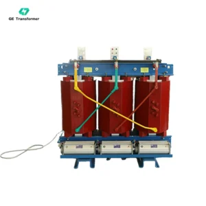
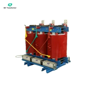
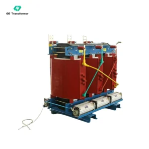
Type: Cast resin dry-type transformer
Primary Voltage Ratings: 6kV / 6.3kV / 6.6kV 10kV / 10.5kV / 11kV 12.47kV / 13.2kV / 13.8kV, 20kV / 22kV / 22.9kV / 24.9kV / 33kV / 34.5kV 35kV, or others
Secondary Voltage Ratings: 480/277V, 400/230V, 380/220V, 550V, 690V, or other
H.V. TAP RANGE: ±2×2.5%
CONNECTION TYPE: Dyn11, Yyn0
Phase: Three-phase
Frequency: 50/60 Hz
Cooling Type: AN,AF,AN/AF
Winding Material: Copper/Aluminum
Enclosure: The enclosure material is available in cold-rolled steel or stainless steel options, with a protection rating ranging from IP23 to IP54.
Standards Compliance: IEC60076, GB20052-2020, ISO9001, ANSI, CSA
Applications: Commercial and institutional buildings, industrial facilities, oil & gas, solar and wind energy, utility grid connections, data centers, and It can also be used in coastal islands and high-altitude regions.
Min. order quantity: ≧ 1 set
Factory Services: OEM, ODM, Customized Voltage, Capacity, Enclosures, and Accessories
Packaging Details: International wooden cases or according to the actual transport needs
delivery time: Generally, it is 20-30 days. It is according to the quantity.
400 kVA dry-type transformer manufactured by GE Transformer is a mainstream medium-small capacity cast resin dry-type transformer with stable comprehensive performance, widely applied in medium and small industrial workshops, large supermarket power distribution rooms, factory branch power supply areas and new energy photovoltaic supporting power systems. Optimized with low-loss silicon steel core and high-efficiency concentric winding structure, this 400kVA dry type transformer effectively cuts no-load loss and running power consumption, greatly improving overall power supply stability. Equipped with standard AN natural air cooling and AF forced air cooling dual cooling system, and optional IP23 to IP54 waterproof and dustproof enclosure, the dry type transformer runs stably all year round in complex industrial and commercial environments. Every unit passes strict factory partial discharge test and high-voltage withstand test, supporting OEM customized voltage and size, ready for bulk export to global power distribution projects.
| No. | Item | Specification |
| 1 | Power Rating | 400kVA |
| 2 | Primary Voltage | 6kV / 6.3kV / 6.6kV 10kV / 10.5kV / 11kV 12.47kV / 13.2kV / 13.8kV, 20kV / 22kV / 22.9kV / 24.9kV / 33kV / 34.5kV 35kV, or others |
| 3 | Secondary Voltage | 480/277V, 400/230V, 380/220V, 550V, 690V, or others |
| 4 | Connection Type | Dyn11, Yyn0 |
| 5 | Phase | Three-phase |
| 6 | Frequency | 50/60 Hz |
| 7 | Insulation Type | Cast Resin |
| 8 | Insulation Class | Class F (155°C),Class H(180°C) |
| 9 | Temperature Rise | 115°C (standard) |
| 10 | Cooling Method | Air Natural (AN), Air Forced (AF) |
| 11 | Short Circuit Impedance | Capacity ≤ 630KVA, 4-6%,Capacity > 630KVA, 6-8% |
| 12 | Voltage Taps | ±2.5%, ±5%, or others |
| 13 | Leakage Magnetic Flux | Low leakage design |
| 14 | Core Material | Cold-rolled grain-oriented silicon steel or amorphous alloy |
| 15 | Winding Material | Copper/Aluminum |
| Altitude | The standard range is 1,000 meters and below; longer ranges are available upon request. | |
| 16 | Operating Temperature Range | -25°C to 40°C |
| 17 | Relative humidity | daily average not exceeding 95%, monthly average not exceeding 90% |
| 18 | Noise Level | ≤55-65 dB(A) |
| 19 | Standards Compliance | IEC60076, GB20052-2020, ISO9001, ANSI, CSA, CE |
| 20 | Common Accessories | Fan, temperature controller, housing, power indicator |
| 21 | Enclosure Material | cold-rolled steel or stainless steel options |
| 22 | Enclosure Protection Rating | IP23 to IP54. |
| 23 | Warranty | Typically one year, depending on the client’s specific needs |
| 24 | Min. order quantity | ≧ 1 set |
| 25 | Packaging Details | International wooden cases or according to the actual transport needs |
| 26 | Delivery Time | Generally, it is 20-30 days. It is according to the quantity. |
| Type | Rated power (kVA) | Winding connection | Voltage combination | No-load loss (W) | On-load loss(W) | No-load current (%) | Short Circuit Impedance (%) | ||
| High voltage | Voltage regulation range | Low voltage | |||||||
| S11-M-30 | 30 | Yyn0 or Dyn11 | 6 6.3 10 10.5 11 | ±5% or ±2×2.5% | 0.4 | 100 | 630/600 | 2.3 | 4.0 |
| S11-M-50 | 50 | 130 | 910/870 | 2.0 | 4.0 | ||||
| S11-M-63 | 63 | 150 | 1090/1040 | 1.9 | 4.0 | ||||
| S11-M-80 | 80 | 180 | 1310/1250 | 1.9 | 4.0 | ||||
| S11-M-100 | 100 | 200 | 1580/1500 | 1.8 | 4.0 | ||||
| S11-M-125 | 125 | 240 | 1890/1800 | 1.7 | 4.0 | ||||
| S11-M-160 | 160 | 280 | 2310/2200 | 1.6 | 4.0 | ||||
| S11-M-200 | 200 | 340 | 2730/2600 | 1.5 | 4.0 | ||||
| S11-M-250 | 250 | 400 | 3200/3050 | 1.4 | 4.0 | ||||
| S11-M-315 | 315 | 480 | 3830/3650 | 1.4 | 4.0 | ||||
| S11-M-400 | 400 | 570 | 4520/4300 | 1.3 | 4.0 | ||||
| S11-M-500 | 500 | 680 | 5410/5100 | 1.2 | 4.0 | ||||
| S11-M-630 | 630 | 810 | 6200 | 1.1 | 4.5 | ||||
| S11-M-800 | 800 | 980 | 7500 | 1.0 | 4.5 | ||||
| S11-M-1000 | 1000 | 1150 | 10300 | 1.0 | 4.5 | ||||
| S11-M-1250 | 1250 | 1360 | 12800 | 0.9 | 4.5 | ||||
| S11-M-1600 | 1600 | 1640 | 14500 | 0.8 | 4.5 | ||||
| S11-M-2000 | 2000 | 2280 | 17820 | 0.6 | 5.0 | ||||
| S11-M-2500 | 2500 | 2700 | 20700 | 0.6 | 5.0 | ||||
Related Products


Related Article
Top 10 Power Transformer Manufacturers in the World: Global Leaders & Trends
The Ultimate Guide to Three-Phase Transformer: Design, Connections, and Efficiency
The Differences Between Power Transformers and Distribution Transformers: Essential Comparisons & Key Details